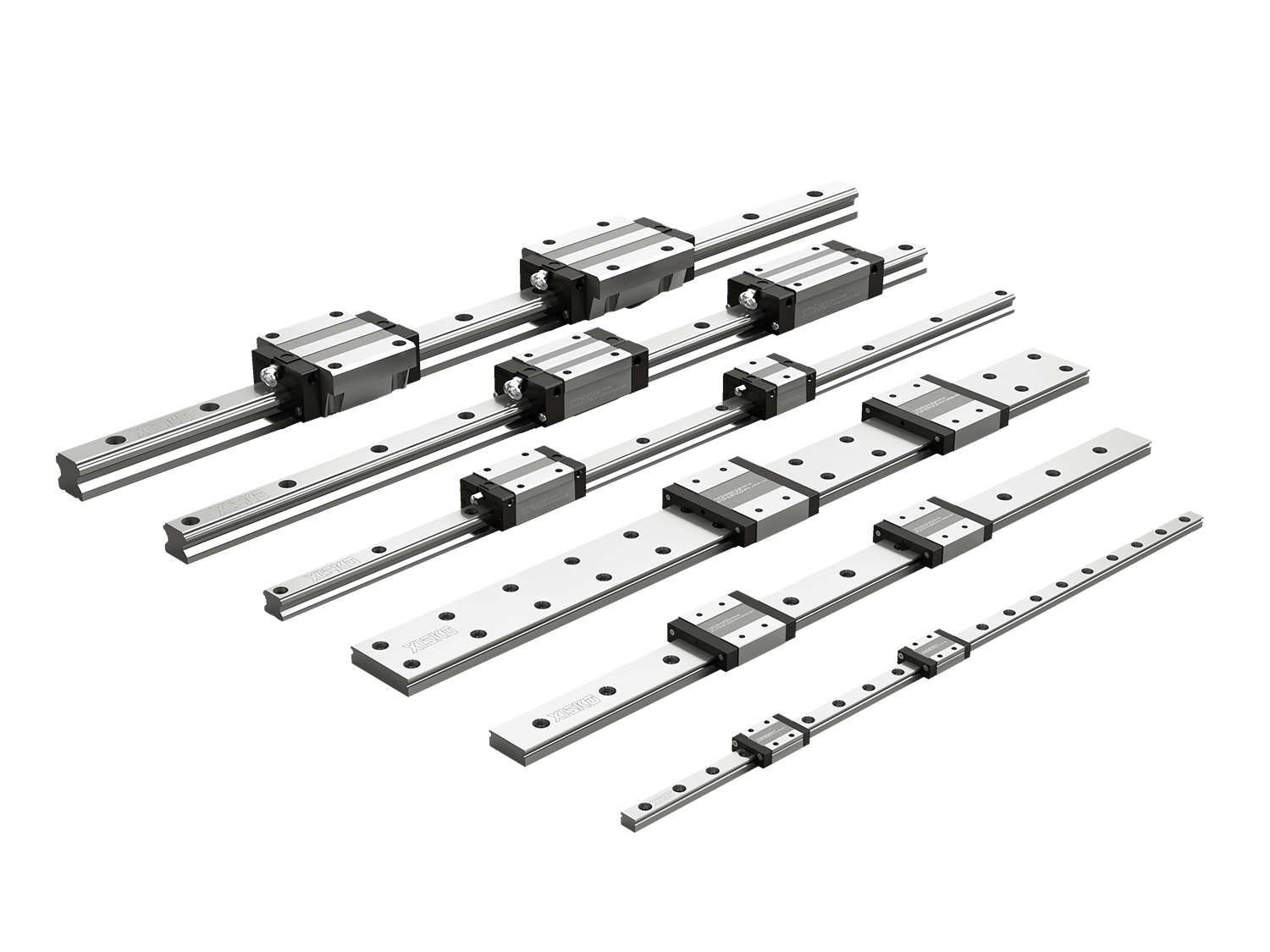


Linear roller rail systems serve as essential core guiding components in high-precision linear motion equipment. This article provides a systematic analysis of the load-bearing capacity of linear roller guide systems, examining fundamental principles, influencing factors, and typical application scenarios.
1. What is the Load-Bearing Capacity of Linear Roller Rails?
LR linear roller rails possess the highest load-bearing capacity and rigidity among all linear guide systems offered by Simkawa.
Compared to standard linear guides, the primary distinction lies in their rolling elements: ball-type linear guides utilize steel balls, whereas roller-type linear guides employ steel rollers. The most significant difference between the two lies in their load-bearing capabilities. Linear roller guides utilize cylindrical roller bearings within their carriages; this configuration creates a large total contact area, enabling them to withstand substantial loads. Conversely, ball-type linear guides utilize spherical ball bearings within their carriages, resulting in a relatively lower load-bearing capacity.
2. Structure and Characteristics of Linear Roller Rail Systems
Because the supporting elements in linear roller guides are cylindrical rollers, the contact interface with the guide rail constitutes a line-to-surface rolling contact. This differs from ball-type linear guides—which utilize spherical ball bearings within their carriages—and accounts for the latter's relatively lower load-bearing capacity.
Due to the large total contact area of the rollers, linear roller guides exhibit higher friction and operate at speeds slightly lower than those of ball-type linear guides; however, this design significantly enhances their rated dynamic and static load capacities. Simkawa linear roller rails can achieve accelerations of up to 100 m/s² and speeds of up to 180 m/min, operating within a temperature range of –10 °C to +100 °C. They are ideally suited for applications requiring high load capacities and high rigidity.
Simkawa linear roller guides deliver exceptional sensitivity and high-performance linear motion. Under heavy or variable load conditions, they exhibit minimal elastic deformation and ensure smooth, stable linear motion, entirely free from the phenomenon known as "stick-slip" (or crawling).
3. Rated Dynamic Load and Rated Static Load
3.1 Safety Factor Verification (Core Requirement)
Linear guide manufacturers provide the rated dynamic load (C) and rated static load (C0). The safety factor must satisfy the following requirements:
Dynamic Load Safety Factor: fsd = C/P ≥ 1.2 (for general operating conditions); for high-speed or high-impact conditions, fsd must be ≥ 1.5–2.0.
Static Load Safety Factor: fss = C0/P0 ≥ 1.5 (for general operating conditions); for high-precision or high-impact equipment, fss must be ≥ 3–5, or even higher.
3.2 Service Life Verification (Optional; Mandatory for Equipment with Long-Term Operation)
The rated service life of a roller-type linear guide refers to the total travel distance at which 90% of the guides will not experience fatigue spalling. The formula is: L10 = (C/P)^(10/3) × 10^6.
Additionally, the general formula applicable to other common types of linear guides is: L10 = (C/P)^3 × 10^6 (Unit: mm), which can be simplified to L10 (km) = (C/P)^3 × 1.
4. Moment Loads
When selecting roller-type linear guides, many people focus solely on the load-bearing capacity in the vertical direction while overlooking moment loads. In reality, within most equipment, the slider is not subjected merely to vertical pressure; it is frequently subjected to eccentric loads (moments).
4.1 Radial Loads
A radial load refers to the load borne by the linear guide in a direction perpendicular to the slider's direction of travel. During operation, the slider typically encounters both lateral and vertical loads; these loads are collectively resolved into radial loads. The magnitude of the radial load depends on the magnitude and direction of the applied load, as well as the dimensions and material properties of the linear guide.
4.2 Thrust Loads
A thrust load refers to the load borne by the LR linear roller rail systems in a direction parallel to the slider's direction of travel. During high-speed motion, the slider may be subjected to significant thrust loads. Therefore, selecting the appropriate guide rail and mounting method is crucial to ensure that the rail can withstand these loads.
4.3 Overturning Moment
The overturning moment refers to the moment generated by the guide rail in the tilting direction. In certain situations, the guide rail may be required to withstand lateral loads, which can cause the rail to tilt. The overturning moment is the moment produced when the guide rail tilts, and it impacts the rail's stability and reliability.

5. Key Factors Influencing the Load-Bearing Capacity of Linear Roller Guides
The load-bearing capacity of a linear roller rail refers to the maximum load it can withstand. This load may be either static or dynamic. The load-bearing capacity of a roller guide is influenced by factors such as its structural design, material selection, and the diameter and quantity of the rollers.
5.1 Roller Diameter
The diameter of the rollers is a critical factor. Generally, the larger the roller diameter, the greater the load-bearing capacity. This is because the roller diameter is directly proportional to its load-bearing capacity. Therefore, provided that the structural design remains sound, prioritizing a larger roller diameter can enhance the load-bearing capacity of the roller guide.
5.2 Rigidity of Roller Linear Guides
The rigidity of a roller guide refers to its ability to resist deformation when subjected to external forces. The greater the rigidity, the less the guide rail deforms under load, thereby enabling it to maintain higher motion precision and stability.
The rigidity of a roller guide is influenced by factors such as its contact rigidity, the arrangement of the rollers, and the structural design of the rail. Among these factors, the roller diameter also plays a role in determining rigidity; larger-diameter rollers possess a larger contact area, resulting in superior rigidity.
5.3 Frictional Resistance
Furthermore, the load-bearing capacity and rigidity of a roller guide are also influenced by its frictional resistance. The lower the frictional resistance, the less energy is lost during the guide rail's motion, thereby enabling more efficient transmission of power and motion. Additionally, the roller diameter is inversely proportional to frictional resistance; that is, the larger the diameter, the lower the frictional resistance. Consequently, by selecting an appropriate roller diameter, it is possible to reduce frictional resistance to a certain extent, thereby enhancing both the efficiency and rigidity of the roller guide.
6. Load-Bearing Requirements Across Different Application Scenarios
6.1 CNC Machining Centers
CNC machine tools impose stringent requirements on the load-bearing capacity, rigidity, and precision of linear roller rail systems. The guides must withstand the weight of the worktable and workpiece, as well as cutting forces and vibration shocks. Roller guides enhance the machine tool's vibration resistance and machining stability, making them ideal for heavy-duty cutting, high-precision machining, and prolonged continuous operation.
6.2 Gantry Machining Equipment
Gantry-style equipment typically features large spans, long travel distances, and heavy loads; consequently, the guide system is susceptible to the effects of eccentric loads and moments. Roller guides possess superior resistance to moments, making them well-suited for use in large gantry milling machines, gantry grinding machines, laser cutting gantry platforms, and heavy-duty handling equipment.
6.3 Automated Production Lines
As mechanical transmission components, Simkawa linear roller rail systems can be seamlessly integrated with other automation devices and control systems to facilitate the construction of automated production lines. Their precise motion control and positioning capabilities contribute to the adaptive adjustment and optimization processes inherent in smart manufacturing.
6.4 Heavy-Duty Handling and Assembly Platforms
In scenarios involving the handling of heavy workpieces, the movement of molds, or mechanical assembly platforms, the guide system must not only support the static weight but also withstand the inertial shocks generated during start-up and deceleration. The high static load capacity and shock resistance of roller guides make them particularly suitable for such operating conditions.
Summary
The load-bearing capacity of a linear roller rail system is determined by a combination of factors, including rated dynamic load, rated static load, moment load capacity, rigidity, preload class, installation precision, and lubrication/protection measures. Compared to ball guides, roller guides—by virtue of their linear contact structure—demonstrate distinct advantages in applications requiring heavy loads, high rigidity, high precision, and shock resistance.
FAQ
1. Which parameters are the primary indicators of a linear roller rail systems load-bearing capacity?
The load-bearing capacity of a linear roller rail systems cannot be assessed solely based on a single "maximum load capacity" figure. A more accurate assessment requires a comprehensive review of the rated dynamic load (C), rated static load (C0), allowable moment, preload class, guide rail specifications, block type, and the number of blocks utilized.
2. Does a higher preload class necessarily equate to superior load-bearing capacity?
Not exactly. Higher preload can enhance the rigidity of a guide rail system, thereby reducing clearance and elastic deformation—factors that are advantageous for high-precision and heavy-duty machining applications. However, excessive preload can also increase frictional resistance, drive load, and operational temperature rise, and may even lead to a shortened service life.
3. How can one determine if a linear roller guide has been undersized?
If the selected guide rail is undersized, the equipment may experience various issues during operation, such as abnormal noises from the slider, motion sticking or binding, increased vibration, reduced positioning accuracy, abnormal temperature rise in the rails, premature wear of the raceways, and a significantly shortened service life for the slider.