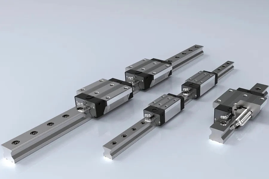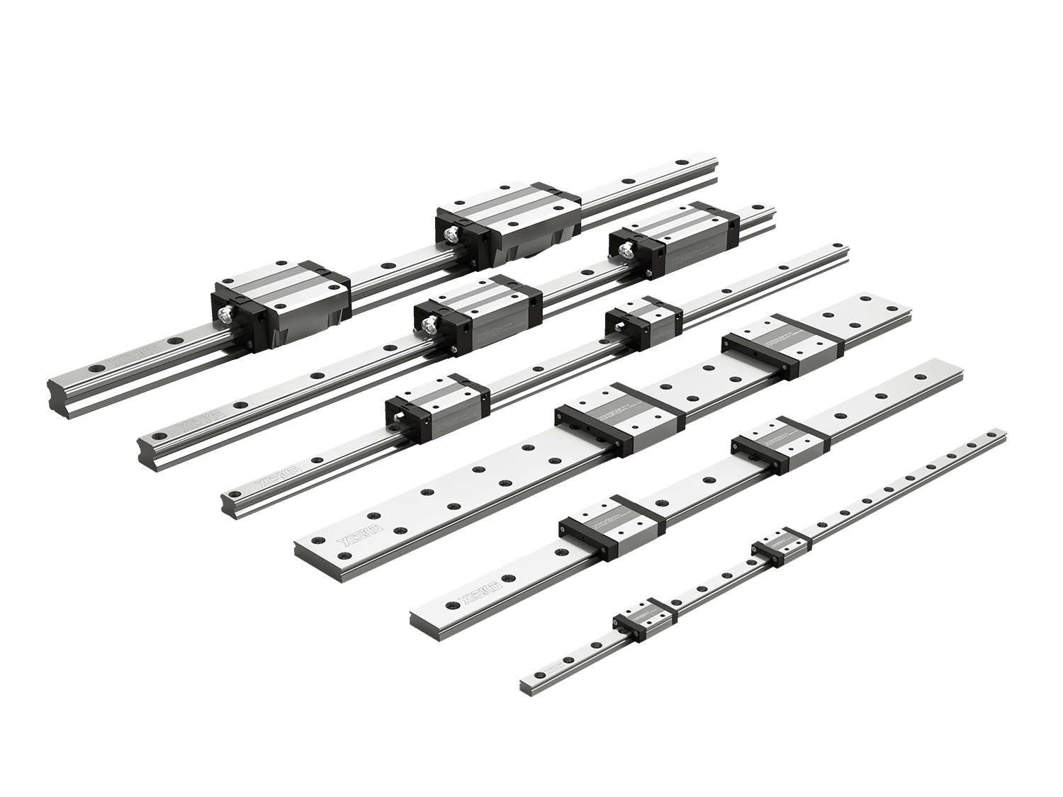


As a core component in modern mechanical transmission systems, linear guides—characterized by their high precision, high rigidity, and low friction—are widely utilized in fields such as CNC machine tools, automation equipment, and semiconductor manufacturing. The following is a detailed analysis of the technical characteristics and lm guideways selection.
1. Core Technical Characteristics of Linear Guides
1.1 High-Precision Positioning Capability
By employing a circulating ball or roller structure, a repetitive positioning accuracy of up to ±0.002 mm can be achieved. Through a preloading design that eliminates clearance—combined with a precision grinding process for the guide rail (achieving a surface roughness of Ra ≤ 0.1 μm)—micron-level motion control is realized, thereby meeting the stringent motion requirements of precision equipment such as lithography machines.
1.2 Four-Direction Equal-Load Design
A unique 45° contact angle structure enables the guide rail to evenly withstand radial, reverse-radial, and lateral loads. Taking a 30 mm wide guide rail as an example, the rated dynamic load capacity can exceed 30 kN, while the static load capacity exceeds 50 kN—performance that is significantly superior to that of traditional sliding guides.
1.3 Self-Lubrication and Long Service Life
Integrated sealing end caps and grease retainers—combined with specialized lithium-based grease—extend the maintenance cycle to a running distance of up to 1,000 km. Constructed from SUJ2 bearing steel that has undergone carburizing and quenching treatment (resulting in a hardness of HRC 58–62), the guides boast a theoretical service life exceeding 10,000 hours.
1.4 Advantages of Modular Installation
Standardized mounting reference surfaces accommodate installation errors of up to ±0.1 mm/m. A leveling process can be rapidly completed using an eccentric bushing adjustment mechanism, thereby reducing installation time by 70% compared to traditional guide rails.
2. Analysis of LM Guideways Selection
2.1 Selection of Accuracy Grade
- Normal Grade (Grade C): Positioning accuracy of ±0.05 mm/m; suitable for packaging machinery.
- Precision Grade (Grade P): ±0.01 mm/m; used in CNC machining centers.
- Super Precision Grade (Grade SP): ±0.003 mm/m; applied in wafer dicing equipment.
2.2 Load Calculation Model
A comprehensive calculation of parameters such as workbench weight (W), cutting force (Fc), and acceleration (a) is required.
Dynamic Equivalent Load P = (W · a + Fc) · Sf, where the safety factor Sf is typically set between 1.2 and 2.0; for high-speed applications, inertial impact must be given additional consideration.
2.3 Speed and Acceleration Matching
- Ball Type: Maximum speed of 120 m/min; acceleration of 0.5 G.
- Roller Type: Speed of 80 m/min; however, acceleration can reach up to 2 G.
- Silent Guide Rails: Feature a special retainer design, resulting in noise levels of <55 dB at a speed of 3 m/s.
3. Selection Cases for Typical Application Scenarios
3.1 5-Axis Machining Center — Recommended Configuration
- Preload Class: Medium Preload (C3).
- Lubrication Method: Centralized oil-air lubrication.
- Protection: Stainless steel scrapers. Field tests demonstrate that, with this configuration, positional fluctuation remains <3 μm at a spindle speed of 20,000 rpm.
3.2 Lithium-Ion Battery Stacking Machine — Key Selection Criteria
- Dust Protection Rating: IP54 or higher.
- Retainer Material: Low-dusting fluoropolymer.
- Integration with Linear Motors: Special attention must be paid to the conductivity treatment of the guide rails.
3.3 Medical CT Equipment — Special Requirements
- Non-magnetic Treatment (SUS440C material).
- Maintenance-Free Design (Fully sealed structure).
- Radiation-Resistant Grease (Fluorinated ether oil base).
4. Maintenance and Fault Prevention
4.1 Vibration Monitoring Standards
Inspection and maintenance are required when the vibration value of the guide rail exceeds the following thresholds
- Low-Frequency Band (<1 kHz): Acceleration > 0.5 m/s².
- High-Frequency Band: RMS velocity > 1 mm/s.
4.2 Wear Warning Indicators
- Indentations exceeding 0.1 mm appear on the raceway contact surface.
- Operating resistance increases by more than 15%.
- The lubricating grease exhibits significant discoloration (Fe content > 100 ppm).
4.3 Regrinding and Repair Process
For precision guide rails, the following methods may be employed:
- Electrolytic dressing to restore rail straightness.
- Laser cladding to repair localized damage.
Following the repair, preload adjustment and run-in testing must be performed anew.
5. Technological Development Trends
5.1 Intelligent Guide Rail Systems
Integrated strain sensors enable real-time monitoring of load distribution, facilitating predictive maintenance via IoT platforms.
5.2 Application of Composite Materials
Carbon Fiber Reinforced Polymer (CFRP) guide rails offer a 40% weight reduction compared to traditional steel guide rails, while their coefficient of thermal expansion is reduced to 0.5 × 10⁻⁶/K.
5.3 Breakthroughs in Magnetic Levitation Guide Rails
A new generation of non-contact guide rails (such as magnetic levitation rails) has achieved nanometer-level positioning accuracy; however, their current cost is approximately 8 to 10 times that of traditional guide rails.
Summary
When lm guideways selection in practice, it is recommended to utilize Life Cycle Cost (LCC) analysis to comprehensively evaluate parameters such as initial procurement costs, energy consumption, and maintenance expenses. For instance, in semiconductor manufacturing equipment operating continuously for 24 hours, selecting high-precision guide rails—despite an initial cost increase of 30%—can reduce annual maintenance expenses by over 60%. Specific selection decisions require multi-objective optimization that takes into account factors such as equipment operating conditions, production cycle times, and environmental parameters.