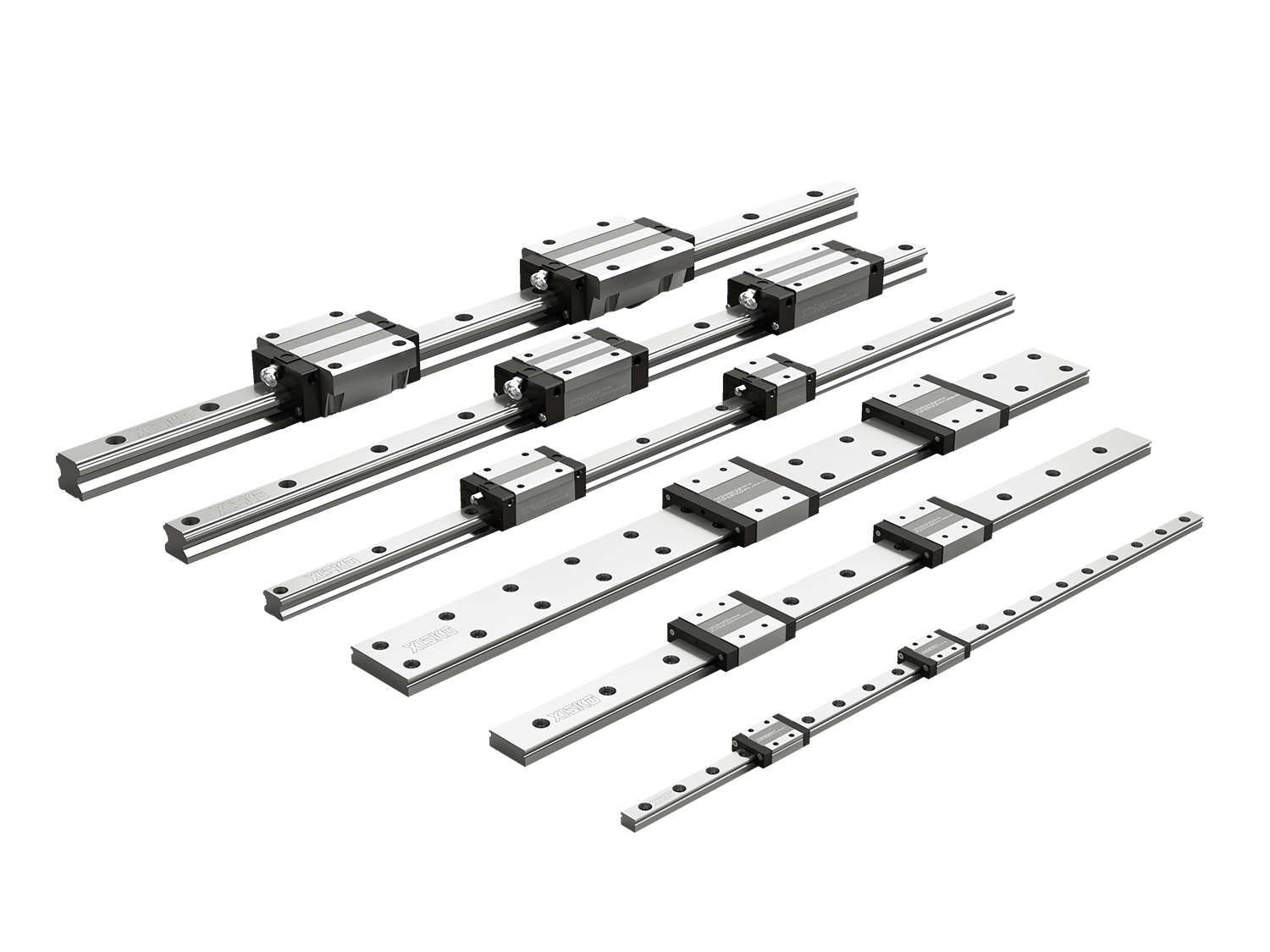
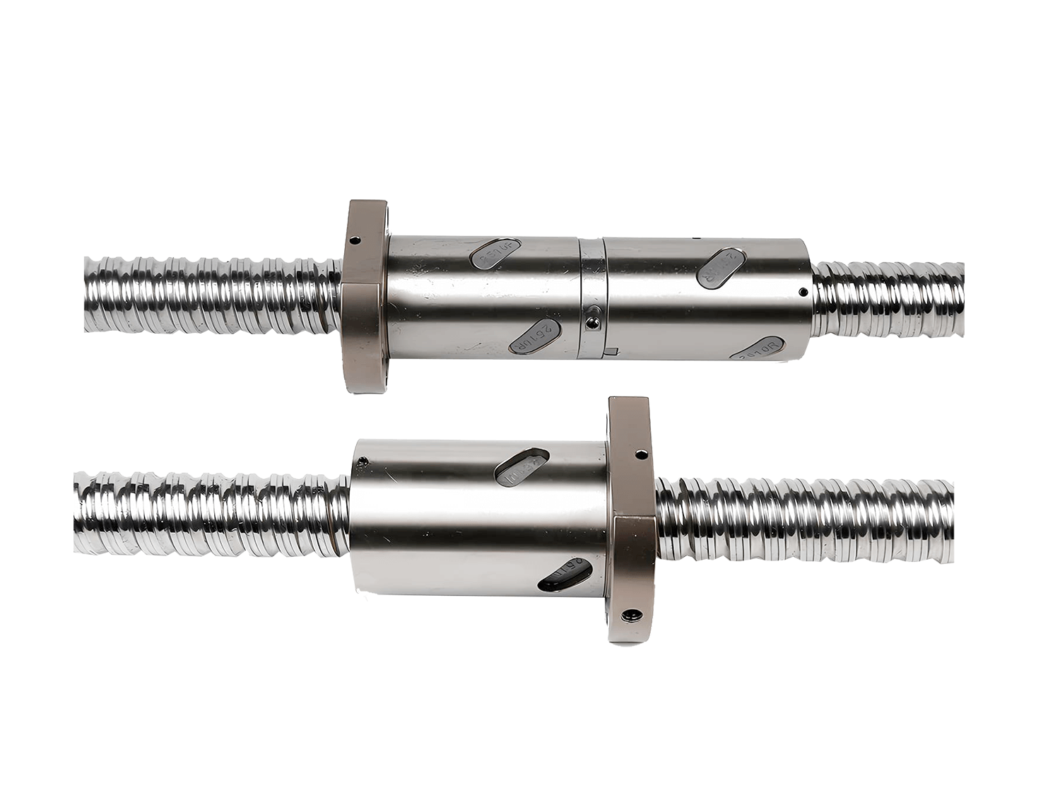

Linear guide assemblies are essential components of mechanical equipment and are widely used in daily life. Therefore, to meet the development needs of linear guide manufacturers, Simkawa has summarized the alignment methods for lm guide rods.
1. Alignment Method
1.1 Straightness Measurement Method and Reference Base Establishment
First, based on a reference linear guide, the reference line is a straight line in space, so the straightness error is measured on two mutually perpendicular planes (horizontal and vertical). The coordinate system is set up the same as the measurement system. Since the guide is rigid and has small deflection, the straightening range cannot be too large. Therefore, the least squares method is used to calculate the straightness error during the straightening process. The least squares centerline is used as the reference line during straightening. When the two LM guide rods are parallel, the least squares centerline is also used as the reference.
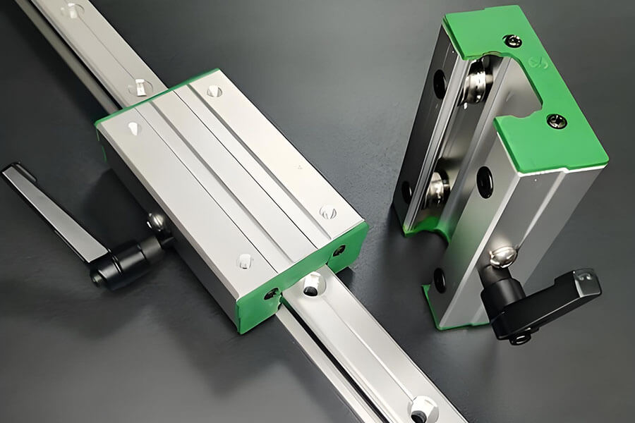
1.2 Contact Form and Adjustment Method Selection between the LM Guide Rod and the Base
The contact between the linear guide and the guide base is a surface contact, and the guide is positioned by mutually perpendicular planes on the base. During alignment, adding material (shim material) to the contact surface of the base is much easier than removing material (grinding or scraping). Therefore, this straightening example uses added material (shim material), but only the accuracy of counting lines can be achieved (due to the thickness limitation of the shim material). To achieve high precision, material must be removed.
1.3 Adjusting the Principles for Selecting Baselines and Determining Limit Points
During the alignment process, the reference line is actually a straight line parallel to the reference guide rail and passing through the limit point. Since the least squares small center line of the reference linear guide rail is used as the baseline, for ease of adjustment, a parallel baseline and a straight line passing through the limit point are selected as the adjustment baseline. Then, the offset of each measuring point relative to the adjustment baseline is calculated, and adjustments are made based on this offset. The limit point on the vertical plane is a larger value; the limit point on the horizontal plane is the larger value of the upper LM guide rod or the smaller value of the lower guide rail (material removal (grinding or scraping) defines the limit point as the exchange of the larger and smaller values). When a straight line parallel to the smaller least squares center line and passing through the limit point is used as the baseline, only the sheet metal is needed to adjust the linear guide rail.
2. LM Guide Rod Calibration Steps
2.1 Align the Reference Guide Rail
- Using a spatial straightness measuring instrument
Measure the straightness error of the guide rail in the horizontal and vertical directions using a spatial straightness measuring instrument, and calculate the offset of the measurement point relative to the least squares center line.
- Determine the straight reference based on the calculation results
Then, according to the offset of the corresponding point, add material at each position and adjust the slide rail to ensure that the straightness error of both planes meets the requirements.
2.2 Second Guide Rail
- Parallelism Straightening
First, measure the straightness error of the LM guide rod and the relative coordinates (offset) of each measuring point (the second guide rail is only fixedly connected to the lower mounting platform); then, use a level to measure the angle difference between the start and end points of the two guide rails (fixed joint), and calculate the height difference in the direction of the start and end points through the angle difference and the distance in length. Use a dial indicator to measure the change in horizontal parallelism of the two slide rail endpoints.
- The adjustment of the second guide rail must be based on the first (aligned) guide rail
The adjustment reference line of the guide rail and the least squares center line of the reference guide rail (the ideal straight reference of the reference guide rail) must be parallel in the vertical direction, that is, the two ideal reference straight lines are coplanar (translating two straight lines from different planes to the guide line can make them parallel in the vertical plane).
Summary
The alignment of the LM guide rod is a key factor in ensuring the mechanical operating performance. By properly controlling the alignment accuracy, the stability, accuracy retention, and service life of the equipment can be significantly improved.