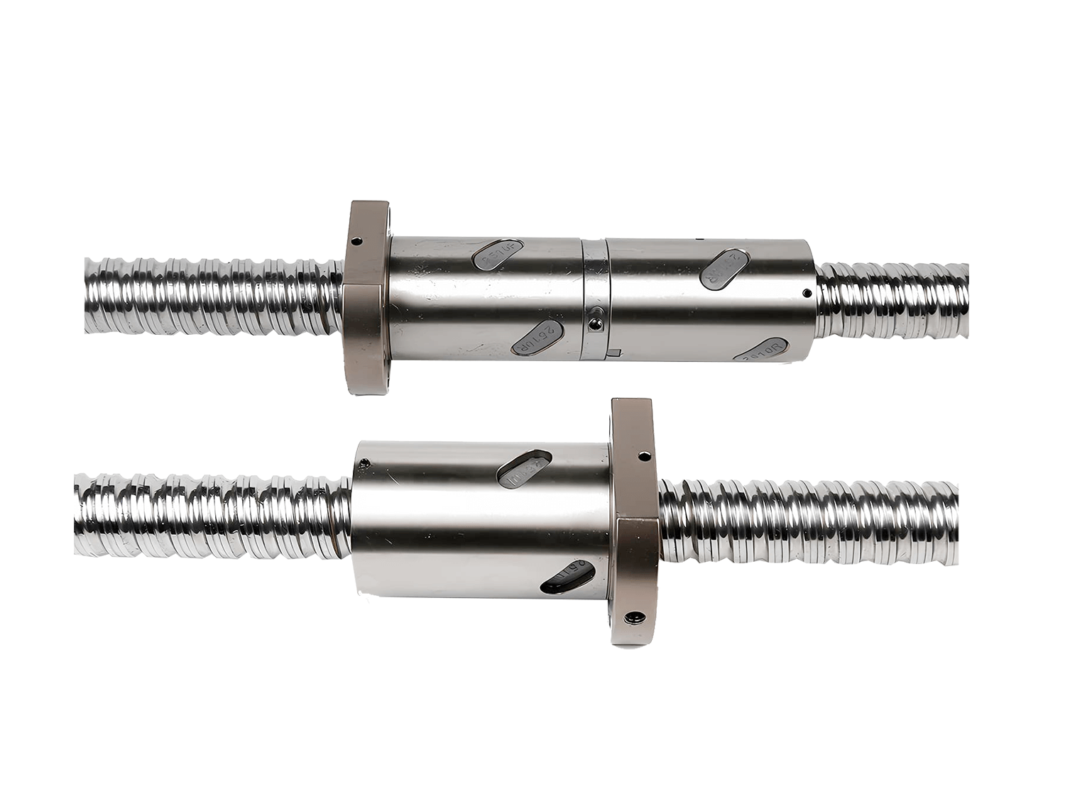

In ball screw systems, the fixing method between the screw and the nut directly determines the system's axial stiffness, thermal expansion compensation capability, and operational stability. Different fixing combinations are suitable for different precision, speed, and load conditions. In actual installation, a reasonable selection must be made based on the equipment structure and requirements. The following are some common ball screw installation methods used in projects and their application instructions.
1. Double-End Fixed, Nut Sliding
1.1 Structural Description
Both ends of the screw are fixed; the nut slides.
1.2 Features
Highest axial stiffness; excellent positioning and repeatability; extremely high requirements for installation alignment and thermal expansion control.
1.3 Applicable Scenarios
High-precision CNC machining centers; short-stroke, high-rigidity feed axes.

2. Fixed–Free, Nut Sliding
2.1 Structural Description
One end is fixed; the other end is autonomous; free sliding.
2.2 Features
Completely releases thermal expansion; low installation stress; relatively low axial stiffness.
2.3 Applicable Scenarios
Long-stroke equipment; transmission systems with significant temperature rise.

3. Supported–Supported, Nut Sliding
3.1 Structural Description
Both ends of the screw are supported; free sliding.
3.2 Features
Simple structure; lacks axial positioning capability; relatively low accuracy and stiffness.
3.3 Applicable Scenarios
Light-load, low-precision transmission auxiliary linear motion mechanisms.

4. Fixed–Fixed, Rotating Screw
4.1 Structure Introduction
- Screw fixed at both ends;
- Nut fixed to moving parts;
- Nut and screw rotate.
4.2 Features
- High transmission accuracy;
- Stable motion;
- Extremely high requirements for bearings and couplings.
4.3 Applications
- CNC machine tool feed systems;
- Precision positioning platforms.

5. Fixed–Supported, Nut Sliding
Most common and recommended industrial installation form.
5.1 Structure Introduction
- One side fixed;
- One side supported;
- Nut sliding.
5.2 Features
- High rigidity and thermal compensation capacity;
- Moderate installation difficulty;
- Excellent overall performance.
5.3 Applications
- CNC machine tools;
- Automation linear modules;
- Industrial machines.

6. Supported–Supported, Symmetric
6.1 Structure Description
- Both sides supported;
- Female stud sliding.
6.2 Features
- No axial position;
- Low sensitivity to device rise error.
6.3 Applications
- Non-positioning transmission;
- Auxiliary mechanisms.

7. Fixed–Free, Load on Nut
7.1 Structure Description
- One side fixed;
- One side free.
7.2 Features
- Clear load path;
- Minimal impact of thermal deformation;
- Suitable for unidirectional loads.
7.3 Applications
- Vertical axis;
- Systems with clearly defined gravity.

8. Fixed–Free, Rotating Screw
8.1 Structure Description
- One side fixed;
- One side free;
- Female stud fixed;
- Screw speed.
8.2 Features
- Can release thermal expansion;
- Compact structure;
- High requirements for motor and alignment.
8.3 Applications
- High-speed feed;
- Precision equipment with structural limitations;
- Female stud directly bears external load.

Summary
These 8 methods of ball screw installation each have their own characteristics in terms of axial stiffness, thermal expansion compensation capability, and installation difficulty. Choosing the right fixing method is a key prerequisite for ensuring system accuracy, stability, and service life.