
In mechanical transmission systems, couplings are a very basic yet crucial connecting component. Their main function is to connect two shafts, enabling the power of the driving shaft to be transmitted to the driven shaft. Based on whether they possess compensation capabilities, couplings can generally be divided into rigid couplings and flexible couplings. This article focuses on rigid shaft couplings.
1. What is a Coupling?
A coupling is like a "connector" between two rotating shafts, installed in the middle of the two shafts to transmit power from one shaft to the other.
Couplings are typically used to connect two shafts and transmit motion and torque between them; they have the ability to absorb vibration and mitigate shock; they can also serve as a safety device to prevent the connected components from bearing excessive loads, providing overload protection; when using a coupling to connect shafts, the two shafts can only be separated after the machine has stopped running and been disassembled.
2. Working Principle of a Rigid Shaft Coupling
The working principle is simple: during operation, it rotates along with the rotating shaft, driving the other shaft to rotate synchronously, thus completing the power transmission. Simultaneously, it can compensate for minor misalignments and offsets during the installation of two shafts, buffer vibrations during operation, prevent wear and damage to shafts and equipment, and ensure smooth operation of the entire transmission system.
3. How does a rigid connection achieve torque transmission?
The key to a rigid shaft coupling's ability to transmit torque lies in the reliable mechanical locking relationship it forms with the shaft. Common connection methods include the following:
The first is the set screw type. This structure has a set screw on the side of the coupling. After tightening, the screw directly presses against the shaft surface, using clamping force and friction to fix the shaft. This type of structure is simple and low-cost, but if the torque is large or there are frequent forward and reverse rotations, indentations may appear on the shaft surface, and slippage may also occur.

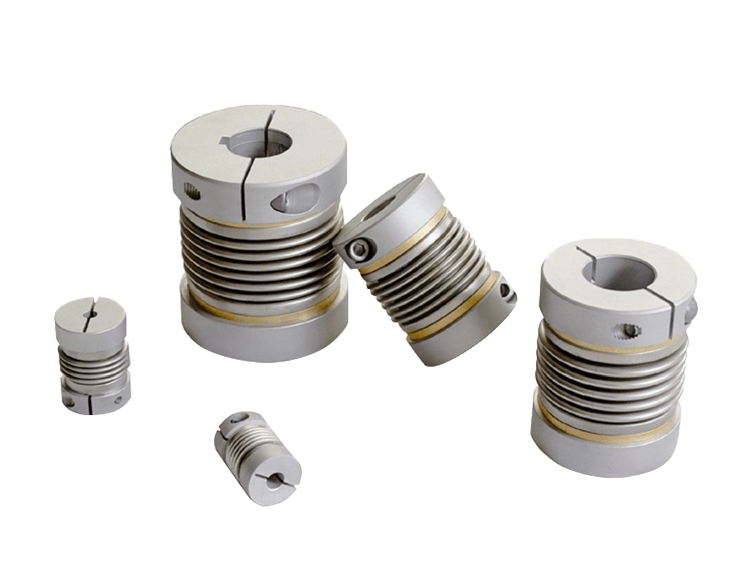
The second is the clamping type. Clamping rigid couplings use a screw to tighten the opening structure, making the inner hole of the coupling evenly grip the shaft surface. Compared to the set screw type, the clamping type causes less damage to the shaft surface and has a more uniform clamping force, making it suitable for applications such as precision transmission, servo motors, stepper motors, and encoders.
The third is the key connection type. When transmitting large torques, a keyway can be machined between the shaft and the inner bore of the coupling, and the torque is transmitted via a flat key. This way, the torque no longer relies primarily on friction, but is transmitted through the mechanical meshing between the key and the keyway, resulting in higher reliability and suitability for heavier-load machinery.
The fourth type is the flange connection. Flange-type rigid couplings typically consist of two half-couplings, each mounted on a separate shaft, and then bolted together with two flanges. It has a robust structure and is suitable for higher power, larger shaft diameters, or heavy-load equipment.
Regardless of the structure used, the essence is to maintain a sufficiently secure connection between the coupling and the two shafts, preventing loosening, slippage, or significant clearance during rotation.
4. Main Advantages of Rigid Shaft Couplings
4.1 Absolute Rigid Transmission
Rigid couplings employ an all-metal design with no elastic elements, directly locking the two shafts with high-strength bolts or flanges to achieve a "rigid connection."
- Extremely high torque carrying capacity: capable of transmitting tens of thousands of Newton-meters of torque, far exceeding that of flexible couplings.
- Zero Torsional Deformation: No elastic buffering, 100% synchronous power transmission, avoiding energy loss.
4.2 Zero Transmission Error
In precision transmissions requiring strict synchronization, rigid couplings offer unparalleled advantages:
- No backlash, no delay: Eliminates phase errors caused by elastic element deformation, ensuring absolutely precise transmission.
- Rigid Vibration Resistance: Resists instantaneous impacts during high-speed operation, preventing positional deviations (e.g., CNC machine tool spindles).
- Case Study: After a high-end CNC lathe was converted to a rigid coupling, the machining roundness error decreased from ±5μm to ±1μm.
4.3 Simple and Durable Structure
The simplified design of rigid couplings results in an exceptionally long lifespan:
Few Parts: Typically composed only of flanges and bolts, with an extremely low failure rate.
- Maintenance-Free Design: No lubrication required; high-temperature and corrosion-resistant materials (e.g., nickel-plated 45# steel, stainless steel) easily withstand harsh environments.
- Cost Advantage: Compared to flexible couplings that require frequent replacement of elastic elements, rigid couplings reduce overall costs by more than 40%.
4.4 Ultra-High-Speed Operation
Rigid couplings perform exceptionally well under extreme operating conditions of tens of thousands of revolutions per minute:
- No Centrifugal Deformation: The integral structure eliminates the risk of components being thrown out during high-speed rotation.
- High Dynamic Balancing Precision: Precision machining and dynamic balancing testing ensure smooth high-speed operation (e.g., turbochargers, aero-engine test benches).
- Data Highlights: After using a rigid coupling, a high-speed centrifugal fan achieved a speed of 18,000 rpm with vibration levels remaining below 0.5 mm/s.
4.5 The "Ultimate Solution" for Stringent Alignment Requirements
While rigid couplings require high installation precision, their advantages become apparent after precise alignment:
- Rigid Compensation for System Errors: Precision machining ensures absolute coaxiality of the two shafts, preventing misalignment during long-term operation.
- Rigid Deformation Resistance: Maintains connection rigidity under heavy load impacts, preventing equipment damage due to shaft deformation.
5. Typical Application Scenarios
Heavy-duty equipment such as metallurgical rolling mills, marine propulsion systems, and mining crushers
5.1 Metallurgical Machinery
For example, the main drive system of a rolling mill needs to transmit torque of thousands to tens of thousands of N·m, requiring zero transmission lag to avoid affecting the rolling precision;
5.2 Mining Machinery
For example, the drive shafts of crushers and ball mills, although subject to certain impacts (which must be controlled within permissible limits), the high-strength structure of rigid couplings can withstand heavy loads, and their maintenance-free characteristics are suitable for harsh mining environments;
5.3 CNC Machine Tools
For example, the spindle of a CNC lathe or machining center is connected to a servo motor. It is crucial to ensure a precise 1:1 torque transmission from the motor to the spindle to avoid dimensional errors caused by backlash (such as pitch deviation in thread machining or flatness deviation in end milling).
5.4 Precision Instruments
For example, the drive shafts of coordinate measuring machines and laser engraving machines require extremely high installation precision (axis alignment error controllable within 0.01mm). Rigid couplings ensure precise execution of motion commands, preventing vibration or backlash from affecting measurement/machining accuracy.
5.5 Semiconductor Equipment
For example, the transmission systems of wafer dicing machines and lithography machines have stringent requirements for speed stability and transmission accuracy. Rigid couplings reduce slippage or lag during transmission, ensuring micron-level precision in wafer processing.
5.6 Turbochargers
In automobiles or construction machinery, the turbine shaft of a turbocharger is connected to the compressor shaft, reaching speeds of tens of thousands of revolutions per minute. Rigid couplings (such as interference-fit sleeve couplings) have no easily damaged parts, can withstand centrifugal forces at high speeds, and offer high transmission efficiency.
Summary
The working principle of rigid shaft couplings is not complex. They use a rigid mechanical connection to fix the driving and driven shafts together, allowing the rotational motion and torque generated by the power source to be directly transmitted to the load end. Their core characteristics are simple structure, high rigidity, high transmission efficiency, fast response, and small backlash, making them suitable for transmission systems with high coaxiality, high precision, and stable loads.
