
During equipment manufacturing or maintenance, the quality of CNC LM guide installation and commissioning directly impacts the machine tool's machining accuracy, service life, and operational stability. Therefore, mastering proper installation and commissioning techniques is essential for mechanical engineers and machine tool assemblers.
1. Pre-Installation Preparation
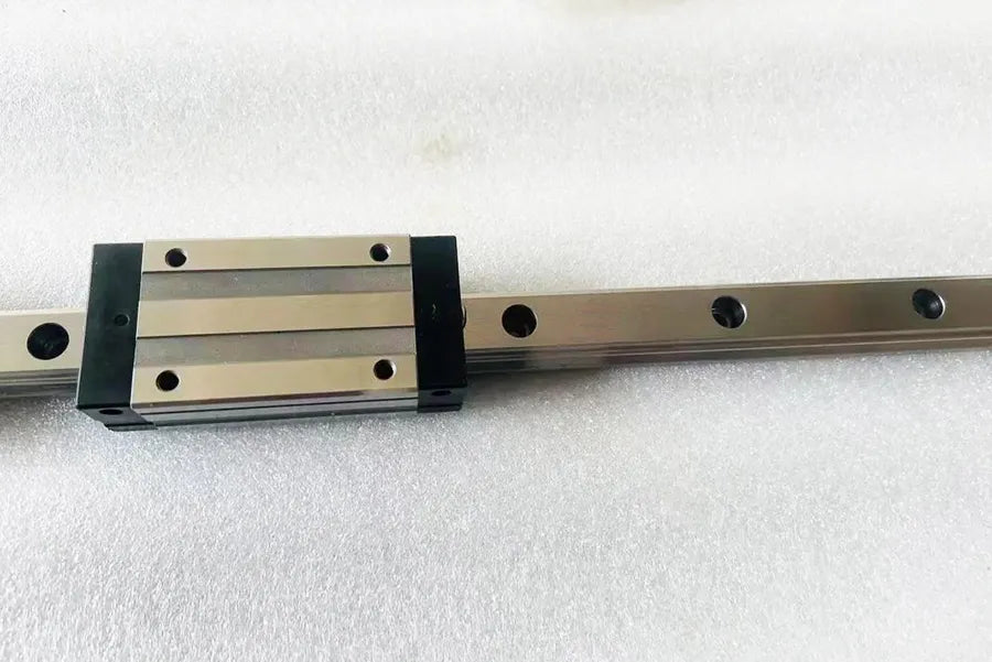
1.1 Inspecting the Guide Rails and Slides
Visual Inspection: Verify that the guide rail surface is free of rust, bumps, or scratches, and that the slides operate smoothly without binding.
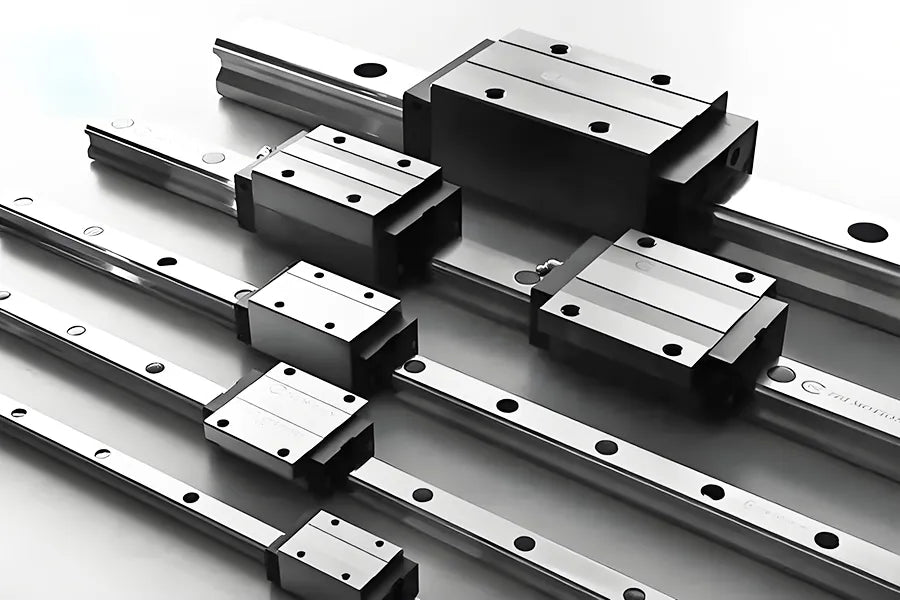
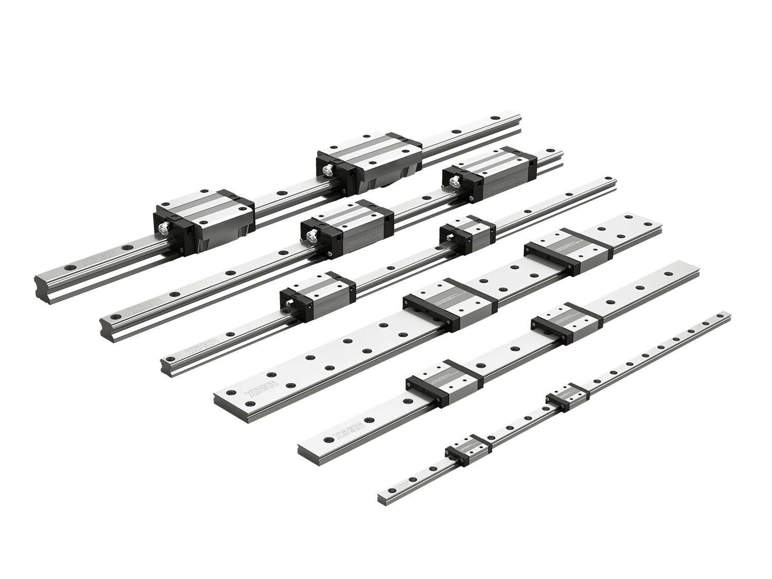
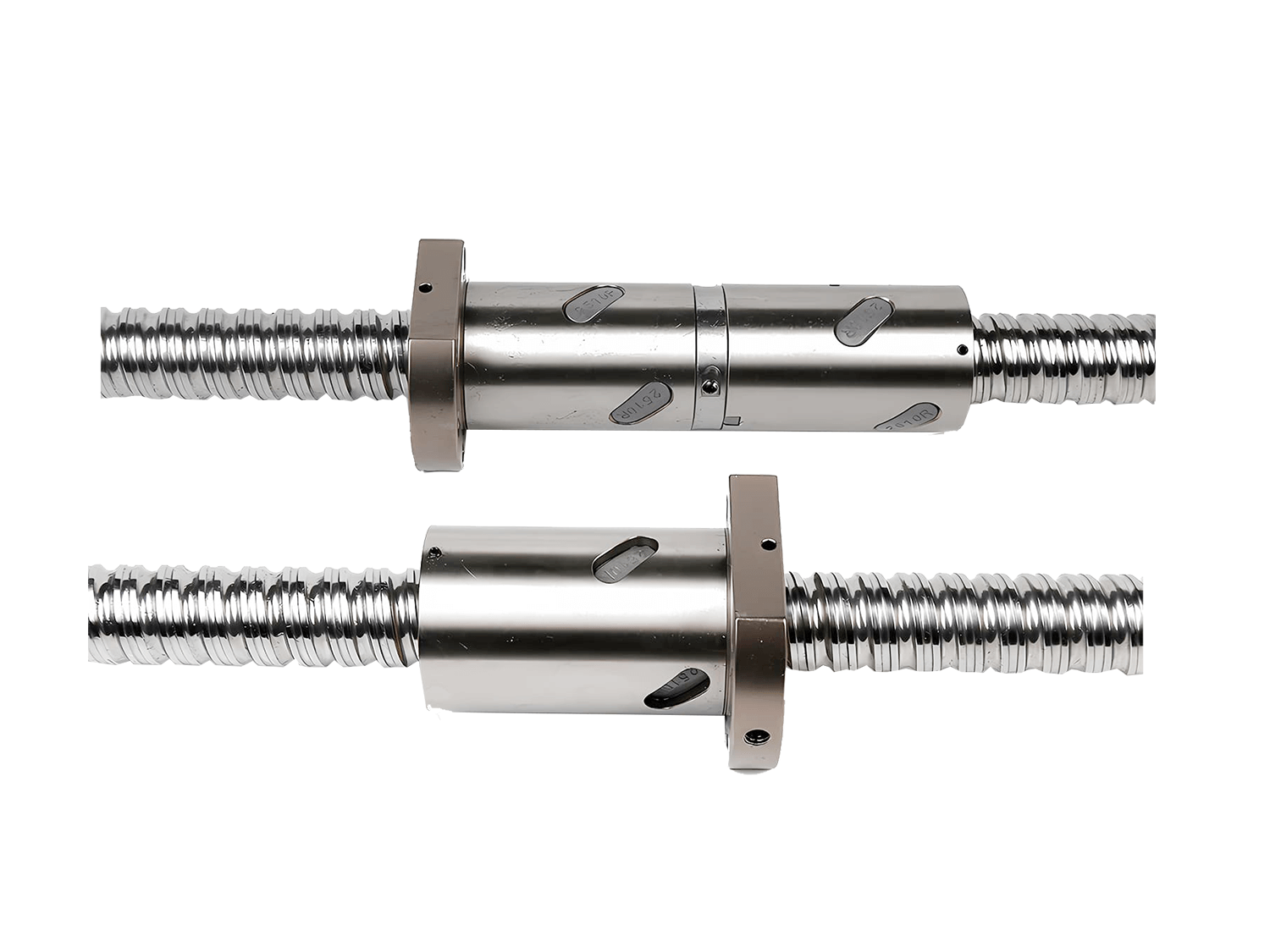
Model Verification: Ensure that the CNC lm guide rail model, length, and accuracy grade meet design requirements.
Accessories: This includes bolts, locating pins, end caps, lubrication nipples, seals, etc.
1.2 Reference Surface Preparation
The reference surfaces (mounting and positioning surfaces) must be precision machined to a surface roughness of Ra1.6 to Ra3.2. Use a precision level to check the flatness and parallelism of the mounting surface. The error should not exceed the manufacturer's specified values (usually within 0.02mm).
Clean the reference surface and remove any chips, dust, and oil to prevent uneven stress after installation.
1.3 Tools and Measuring Instruments
- Torque wrench (for controlling the torque of the tightening bolts);
- Precision level, micrometer, feeler gauge;
- Lubricating grease, clean cloth, and dust-free paper.
2. Installation Steps
2.1 Positioning the Guide Rail
Place the CNC lm guide rail on the reference surface and gently press it against the locating surface until the guide rail locating surface is firmly in contact with the machine tool reference surface. Do not tighten the bolts at this stage to allow for fine-tuning later.
2.2 Pre-tightening the Fixing Bolts
Tighten the fixing bolts on the guide rail sequentially, starting from the center and working toward the ends. Tighten only to 50%-70% of the rated torque, maintaining a certain amount of adjustment margin.
Use a feeler gauge to check for play at the bottom of the guide rail. If any play is present, readjust the reference surface or replace the shims.
2.3 Parallelism and Straightness Adjustment
Install the slider on the CNC lm guide rail and use a dial indicator to measure the slider's straightness relative to the reference during operation.
If the parallelism error is large, correct it by adding a thin shim between the CNC lm guide rail and the reference surface.
When installing two parallel guide rails, first secure one side as the reference rail, then install the floating rail on the other side to ensure smooth slider operation.
2.4 Final Bolt Tightening
After adjustment, use a torque wrench to evenly tighten each bolt to the specified torque value to prevent uneven force on the guide rail and deformation.
3. Commissioning Key Points
3.1 Slider Running Resistance Check
Manually push the slider through its full travel; there should be no noticeable resistance fluctuations or sticking points.
If uneven resistance is observed, it may be a problem with parallelism, straightness, or uneven bolt tightening, requiring readjustment.
3.2 Preload Adjustment
CNC LM Guides typically achieve rigidity control through varying levels of slider preload.
Excessive preload increases friction and heat, shortening life; insufficient preload results in excessive clearance and insufficient rigidity. Select the appropriate preload level according to the manufacturer's recommendations and verify this during commissioning using a thrust meter or current monitoring.
3.3 Lubrication and Protection
Immediately after installation, apply grease (lithium-based grease or specialized guideway oil) and allow the slide to reciprocate to evenly distribute the lubrication.
In environments exposed to dust and cutting fluid, it is recommended to install a protective cover or scraper to extend the life of the guideway.
4. Maintenance Recommendations
- Regular Lubrication: Relubricate every 500-1000 hours, depending on the operating environment.
- Dust and Chip Prevention: Prevent iron chips and dust from entering the rolling elements.
- Inspect the fixing bolts: Prevent loosening caused by long-term vibration.
- Regular Accuracy Inspection: Measure running straightness and clearance annually with a dial indicator and make timely corrections.
Summary
The installation and commissioning of CNC lm guides requires extremely high precision and attention to detail. Proper installation not only ensures machine tool accuracy but also extends the service life of the guideway and the entire machine.